Deep-Sky (DSO) Imaging
Deep-sky objects (DSOs) — nebulae, galaxies, star clusters, and other targets that lie beyond the Solar System with low surface brightness and relatively large angular size. Their surface brightness is usually far below the sky background, so they cannot be captured with the short-exposure, high-frame-rate “lucky imaging” methods used for planets. Instead they rely on accumulating faint photons over long periods and stacking many images to raise the signal-to-noise ratio. This leads to the two core requirements of deep-sky imaging: precise tracking of the target, and a sufficiently long total integration time. This page describes the complete acquisition chain — from tracking, guiding, and sub-frame strategy to calibration, focusing, framing, and sequence automation. Post-stacking and stretching are out of scope here; see Stacking and Post-Processing.
Tracking and Guiding
Section titled “Tracking and Guiding”The Earth rotates at about 15 arcseconds per second (15”/s, i.e. 15°/h), causing celestial objects to undergo a diurnal apparent motion across the celestial sphere (see The Diurnal Apparent Motion of Celestial Objects). To keep stars as points rather than trails over an exposure of several minutes, a drive system must counteract this motion in the opposite direction.
- Tracking: an equatorial mount rotates uniformly about its polar axis at the sidereal rate, cancelling the diurnal motion. This is the minimum requirement for deep-sky exposures. For wide-field starscapes at short focal lengths, tracking alone can yield fairly long, trail-free exposures.
- Guiding: an auxiliary camera monitors the position of a guide star in real time, converts its drift into a correction sent back to the mount, and closed-loop corrects the residual tracking error. The longer the focal length and the longer each sub-frame, the more the tracking error accumulates and the more indispensable guiding becomes.
Tracking errors in an equatorial mount come mainly from three sources: periodic error (PE) from the worm-gear drive, drift and field rotation caused by imprecise polar alignment, and random or slowly varying factors such as wind disturbance, imbalance, and atmospheric refraction. Guiding can suppress the camera-observable portion of the first two, but it cannot compensate for the field rotation caused by a severe polar misalignment.
Guide Scope vs. Off-Axis Guiding
Section titled “Guide Scope vs. Off-Axis Guiding”There are two ways to feed light to the guide camera, each with trade-offs.
| Method | Light Source | Advantages | Limitations |
|---|---|---|---|
| Guide scope | A separate small telescope mounted alongside the main scope | Wide field, easy to find a guide star, simple to install, does not obstruct the main optical path | Differential flexure exists between the guide scope and the main scope; at long focal lengths this shows up as elongated stars in the main image |
| Off-axis guider (OAG) | A small prism in the main optical path picks off a thin beam of light from the edge | Shares the main optical path, automatically accounting for tube flexure and mirror shift, with no differential flexure | Small field, fewer usable guide stars, requires precise focusing so the guide star and the main scope focus simultaneously, and is more fiddly to set up and adjust |
As a rule of thumb, with a main focal length below about 1000 mm and good mechanical rigidity, a guide scope is usually sufficient; at longer focal lengths (often taken as 1500–2000 mm as a threshold), or when using scopes prone to mirror shift such as Schmidt-Cassegrains (SCTs), the common-path advantage of an OAG is clear and it is almost a necessity for long exposures.
Guiding Software and RMS Error
Section titled “Guiding Software and RMS Error”PHD2 (Push Here Dummy 2) is a widely used open-source guiding application. Its workflow is as follows: select a guide star of moderate brightness that is unsaturated and isolated, then perform calibration — issue pulses of known duration along right ascension (RA) and declination (Dec) and measure the guide star’s displacement on the sensor, thereby establishing both the “pulse duration ↔ actual angular displacement” relationship and the correspondence between the camera axes and the mount axes; thereafter, each frame measures the guide star’s centroid offset and issues correction pulses.
Guiding accuracy is measured by the root-mean-square error (RMS), usually quoted in both arcseconds (arcsec) and pixels. The total RMS is the combination of the RA and Dec axis components. A rule of thumb is that the guiding RMS should be noticeably smaller than the angular sky scale corresponding to a single pixel of the imaging system, so that the spread of star points is determined mainly by atmospheric seeing rather than tracking error. A common target is a total RMS between 0.5” and 1.5”; under good seeing with an excellent mount, sub-0.5” can be achieved.
Sub-Frame Strategy and Total Integration Time
Section titled “Sub-Frame Strategy and Total Integration Time”Deep-sky imaging usually does not take a single ultra-long exposure but instead collects a large number of moderate-length light frames (exposures aimed at the target that accumulate signal), then stacks them. There are three reasons: the longer a single frame, the more it is ruined by a satellite trail, a gust of wind, a tracking hiccup, or aircraft lights, and the greater the loss; many shorter frames make it easy to reject bad frames by quality; and stacking effectively suppresses uncorrelated random noise.
Signal-to-Noise Ratio and Frame Count
Section titled “Signal-to-Noise Ratio and Frame Count”When stacking, the target signal adds coherently while random noise adds incoherently, so the signal-to-noise ratio (SNR) grows as the square root of the effective frame count N:
SNR ∝ √NTherefore quadrupling the number of frames roughly doubles the SNR; equivalently, doubling the total integration time improves the SNR by about a factor of 1.41 (√2). This means returns diminish with time, but the total integration time is always the dominant factor determining the final image quality, and deep-sky targets often require accumulating several hours, sometimes spread over multiple nights. For the full derivation of SNR, see SNR Principles.
Choosing the Sub-Exposure Length
Section titled “Choosing the Sub-Exposure Length”The sub-exposure length should balance two constraints: long enough to be “sky-limited” — that is, the sky-background shot noise exceeds the camera’s read noise, so read noise becomes negligible in the stack; yet short enough to avoid saturating and clipping bright stars and the highlight regions of the target, and to reduce the loss when a single frame is ruined. On modern low-read-noise CMOS cameras the following values can serve as a starting point; the actual choice also depends on aperture, sky brightness, camera gain, and filter bandwidth.
| Scenario | Typical Sub-Exposure | Notes |
|---|---|---|
| Urban / heavy light pollution (broadband RGB) | 30–120 s | Sky glow is strong; too long fills the background quickly and bright stars saturate easily |
| Dark sky (broadband RGB) | 120–300 s | The common range for most deep-sky targets |
| Narrowband (Hα / OIII / SII) | 300–900 s | Narrowband filters block the vast majority of sky glow, so longer exposures are needed to become sky-limited |
Once the sub-exposure length is fixed, total integration time = sub-exposure length × effective frame count. A common configuration is something like 180 s × 80 frames ≈ 4 hours. Gain/ISO and cooling temperature should also be fixed so that calibration frames can be reused.
Dithering and Walking Noise
Section titled “Dithering and Walking Noise”Dithering means that, between certain frames, the imaging software directs the guiding system to make the mount perform a small, randomly directed shift (typically a few to a dozen-plus pixels of the imaging camera) so that the target lands on different pixels of the sensor in the next frame. Dithering is led by the imaging software, because only it can pause the main camera exposure during the shift; the guiding software is responsible only for executing the guide pulses needed for the shift.
The purpose of dithering is to break up fixed-pattern noise tied to sensor position, including hot pixels, dead pixels, and dark-current non-uniformity. When stacking with frame-to-frame offsets registered, these blemishes — which do not align with the celestial target — are distributed to different positions across many frames and removed by algorithms such as median or sigma clipping.
Dithering targets walking noise in particular: when the mount has a slow, constant drift in some direction (commonly from a slight polar misalignment or a one-way slow drift of the Dec axis), the fixed-pattern noise marches along that direction frame by frame, producing colored streaks or “rain-like” texture extending along a fixed direction after stacking. Random dithering interrupts this regular drift so it cannot accumulate coherently. A common practice is to dither every 1–3 frames; the longer the focal length or the more visible the pattern noise, the larger the dither amplitude should be. Dithering is recommended throughout deep-sky acquisition.
Calibration Frames
Section titled “Calibration Frames”The camera and optical path introduce repeatable systematic blemishes: dark current and hot pixels, vignetting and shadows from the tube or dust, pixel gain non-uniformity, read-out pedestal, and so on. Calibration frames are used to measure these blemishes and subtract them from the light frames before stacking. They add no target signal themselves, but they significantly improve the uniformity and cleanliness of the stacked result. The three basic types of calibration frame are as follows.
| Calibration Frame | How It Is Taken | What It Corrects |
|---|---|---|
| Dark frame | With the optics covered (lens cap on), at the same exposure length, temperature, and gain as the light frames | Dark current, hot pixels, and the fixed dark-signal pattern |
| Flat frame | Exposed against a uniformly illuminated panel or the twilight sky, with the same optical path and focus as the light frames | Vignetting, dust shadows, and pixel-to-pixel sensitivity differences |
| Bias frame | With the optics covered, using the shortest possible exposure of the camera | The read-noise pedestal and the sensor’s read-out bias |
The basic operation for applying calibration can be expressed as (R is the raw light frame, D the dark frame, F the flat frame, and m the flat normalization constant):
Calibrated = (R − D) × m / (F − D_flat)That is, first subtract the dark frame to remove thermal signal and the pedestal, then divide by the (dark/bias-corrected) flat frame to normalize sensitivity and illumination non-uniformity. Dark and bias frames can be pre-built at the same temperature and gain as master darks / master biases and reused over the long term; flat frames must be taken when the current optical path (including focus, camera rotation angle, and filter) has not changed, because vignetting and dust positions change as the optical path changes. For detailed methods, see Calibration Frames.
Focusing, Framing, and Plate Solving
Section titled “Focusing, Framing, and Plate Solving”Focusing
Section titled “Focusing”The depth of focus in deep-sky imaging is extremely small, the focus tolerance is very tight, and temperature changes cause the focus to drift, so focus must be rechecked or automatically refocused during acquisition. There are three common criteria.
- Bahtinov mask: a diffraction grating placed in front of the aperture; when aimed at a bright star it forms three sets of diffraction spikes (two fixed sets forming an “X” and one movable central streak). Focus is achieved when the central streak passes exactly through the intersection of the X (symmetrically centered). It is intuitive to read and well suited to manual focusing; software can analyze the offset of the central streak to sub-pixel precision.
- Half-flux radius (HFR): the radius within which half the energy of a star point falls; the smaller the value, the sharper the focus. Software such as N.I.N.A. measures the HFR at several focuser positions, fits a V-curve, and automatically finds the optimal focus corresponding to the minimum HFR.
- Full width at half maximum (FWHM): the full width of a star’s brightness profile at half the peak value; likewise, the minimum value corresponds to best focus. FWHM is also commonly used to quantify the seeing over the course of a night.
An electronic focuser combined with temperature compensation and timed autofocus can continuously maintain focus throughout a long sequence.
Framing
Section titled “Framing”Framing computes the field of view (FOV) from the main focal length and sensor size, places the target in an ideal position and leaves a composition margin; rotating the camera adjusts the angle of the frame so the target’s long axis matches the frame or includes surrounding objects. For the relationship between FOV and focal length / pixel size, see Focal Length and Field of View. To plan a target’s visibility and culmination altitude, refer to Hemisphere Visibility and Observing Conditions.
Plate Solving
Section titled “Plate Solving”Plate solving means having software perform a star-pattern match on a test exposure to automatically solve for its precise right-ascension/declination pointing and rotation angle (see The Celestial Coordinate System). Its uses include: closed-loop correction of the mount’s pointing (goto) error to center the target precisely; reproducing the camera rotation angle and central coordinates to match existing data when imaging across multiple nights, making the framing consistent for stacking; and automatically returning to position after a meridian flip. Plate solving is faster and more repeatable than manual star-hopping, and it is the core element of automated acquisition.
A Typical Night’s Workflow
Section titled “A Typical Night’s Workflow”The following are representative steps for a single night of deep-sky acquisition. The exact order and degree of automation depend on your equipment and software.
- Set up the mount, complete counterweight balancing and mechanical locking; roughly align toward the north/south celestial pole.
- Perform polar alignment (drift method, electronic polar scope, or software three-point method), reducing the polar-axis error to an acceptable range.
- Use a Bahtinov mask or software autofocus to bring focus to its best (minimum HFR/FWHM, or the central diffraction streak centered).
- Plate solve + goto to center the target precisely, rotate the camera to set the framing, and refocus if necessary.
- Start guiding: select a guide star, calibrate, run the guiding assistant assessment and confirm the total RMS is within an acceptable range; enable flip calibration on meridian flip.
- Set up the acquisition sequence (sub-exposure length × frame count, filter order, autofocus triggers, meridian flip, dither interval) and begin acquiring light frames.
- When the sequence ends or dawn approaches, take flat frames while the optical path is unchanged; dark and bias frames can use pre-stored master frames at the same temperature and gain.
- After bringing the data home, complete calibration, registration, stacking, stretching, and final image production in Stacking and Post-Processing.
Sequence Automation
Section titled “Sequence Automation”A mature acquisition session is usually orchestrated by software that strings the above steps into an unattended sequence. Common options:
- N.I.N.A. (Nighttime Imaging ‘N’ Astronomy): open-source Windows software whose “advanced sequencer” graphically orchestrates focusing, plate-solve recentering, guiding, dithering, filter switching, meridian flip, automatic flat capture, and linkage to safety conditions (cloud cover/rain), guiding in concert with PHD2.
- ASIAIR: a Raspberry Pi-based all-in-one control box that controls compatible cameras, mounts, and electronic focusers via a phone/tablet app, with built-in guiding, plate solving, and sequencing. It is portable and quick to learn, but device compatibility is limited by the vendor’s ecosystem.
Both rely on plate solving for automatic recentering and post-flip repositioning, on autofocus to maintain focus all night, and on linkage with guiding software to perform dithering.
Remote Platforms
Section titled “Remote Platforms”A mount that tracks and guides reliably, a cooled camera, and a sufficiently dark sky together represent a high barrier and cost. If building your own setup is not yet practical, remote observatory platforms are a good way to start: professional equipment installed at premium dark-sky sites in Chile, Spain, the southwestern United States, Australia, and elsewhere, where you submit exposure sequences over the network or directly obtain already-acquired data and then process it yourself. Representative services include the subscription-based Telescope Live, the pay-per-use iTelescope, and a number of equipment-hosting providers. This path decouples “learning to process deep-sky data” from “accumulating gear,” and is well suited to first mastering acquisition strategy and the post-processing workflow. For details, see Remote Observatory Platforms and Platform Comparison.
Common Pitfalls
Section titled “Common Pitfalls”- Chasing ever-longer sub-frames only: once sky-limited, continuing to lengthen the sub-frame improves SNR far less than increasing the total frame count, while raising the loss from ruined frames and the risk of saturation. What determines image quality is the total integration time.
- Not dithering: even with dark-frame correction, the lack of dithering still leaves sensor-bound texture such as walking noise, which stacking cannot remove.
- Ignoring polar alignment and relying on guiding to fix it: guiding cannot correct field rotation; the cause of arc-shaped stars toward the edges is usually polar-axis error, not guiding parameters.
- Reusing flats after the optical path changes: after rotating the camera, refocusing, or dust moving, old flats introduce new vignetting/dust mismatches and must be retaken for that session.
- Not flipping calibration after the meridian flip: after the flip the RA correction direction is reversed, causing guiding to lose control rapidly.
Sample Image
Section titled “Sample Image”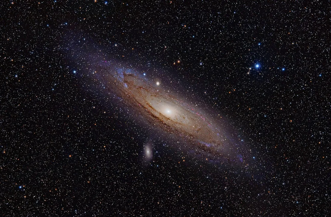
With the fundamentals in place, you can advance to Narrowband Imaging to shoot emission nebulae under urban light pollution, or revisit SNR Principles to understand why a longer total integration time yields a cleaner result. For term definitions, see the Glossary.
References
Section titled “References”- Astrophotography — Wikipedia: an overview of astrophotography, covering the basic principles of long exposure, tracking, guiding, and multi-frame stacking.
- Flat-field correction — Wikipedia: the definition of flat-field correction, the roles of dark/flat/bias frames, and the calibration formula.
- PHD2 User Guide / Tools: calibration, guiding RMS measurement, and the dithering mechanism in the open-source guiding software PHD2.
- Guide Scope vs. Off-Axis Guider — OPT: a comparison of differential flexure and suitable focal lengths for guide scopes versus off-axis guiders.
- Auto-Focus — N.I.N.A. Documentation: the principles of HFR-based autofocus and focus triggering in sequence automation.
- iTelescope — Remote Astrophotography Platform: an example of a remote telescope network, supporting online setting of exposures, filters, dithering, and plate solving.